In today’s world, where the number of wireless connected devices and applications become uncountable, control and efficient use of the available RF Spectrum is important.
In order to achieve this, most countries in the world now use complex digital RF communication with associated highly technical and pricey Hardware.
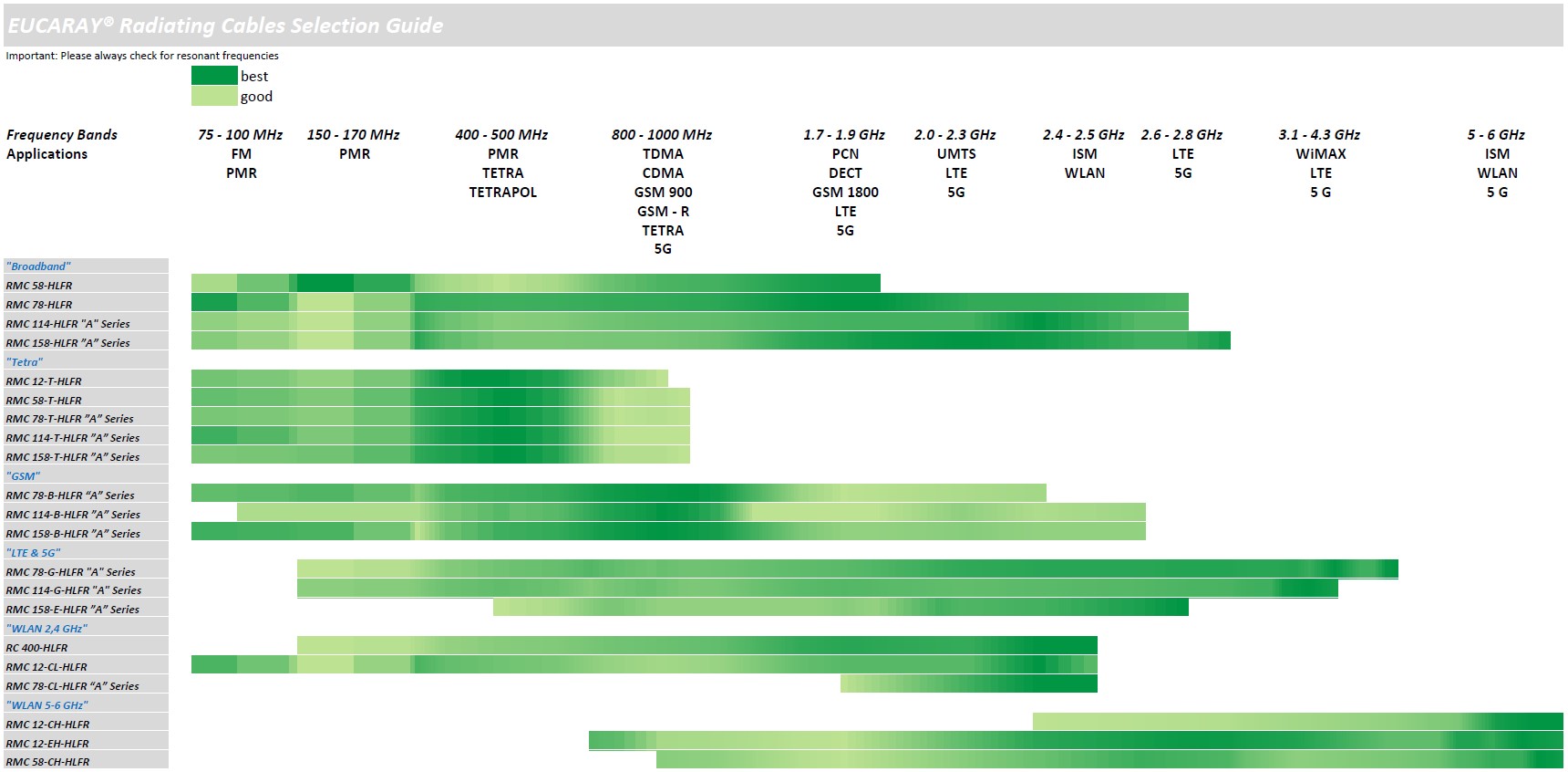
Radiating Cables are commonly used for a wide variety of applications and frequency bands from 30MHz to 6Ghz.
Whilst EUCARAY® Radiating Cables inherently are broadband, modern manufacturing techniques make Band Optimised versions possible. Selecting the most suitable EUCARAY® Radiating Cable will result in an increased Repeater spacing, decreasing Hardware cost and, thus, outweighing any alleged saving made by using technically inferior Radiating Cables.

EUCARAY® Radiating Cable Choice:
Eupen offers a wide range of broadband or frequency band optimised EUCARAY® Radiating Cables:
- LSC cables for applications up to 1GHz without any frequency restriction
- RMC “A-Series” for applications up to 3.5 GHz
- RMC “T” cables optimized for Tetra (380 – 470 MHz) applications
- RMC “B” cables optimized for GSM-R, FRMCS & Tetra (also 870 MHz)
- RMC “E” cables optimized for LTE (up to 2700 MHz)
- RMC “CL” & “CH” for WLAN (2.4 and 5.8Ghz)
- RMC “G” cables optimized for 5G & LTE (700 to 3800MHz)
According to the Frequency Band required by the application, the quick Cable Selection Guide below and the EUCARAY® Products on this website will allow a preliminary cable selection
Comparing Cable Performances:
Coupling Losses (C50 or C95) and Longitudinal Losses are the most important parameters.
While the Longitudinal Loss is in direct relation with the cable size, the coupling loss will depend on the cable slot design.
To compare the performance of different cables, the sum of the Coupling Loss and the Longitudinal Loss over 1000m (or any other relevant distance for the particular application) can be very helpful.
Example at 450 MHz, for 1000m cable, with C95 coupling loss:
– Cable type RMC114 “A-Series” : 73 dB + 10 x 2,2 dB/100m = 95 dB loss
– Cable type RMC114-T : 58 + 10 x 2,1 (dB/100m) = 79 dB loss
– Cable type RMC78-T : 53 + 10 x 3,3 (dB/100m) = 86 dB loss
This example shows the importance of choosing the appropriated cable design, as the optimised smaller 7/8″ size cable will in this case perform much better than the bigger 1-1/4″ broadband cable.
It has to be noted that Eupen always publishes the Average Coupling Loss according IEC 61196-4, thus the average over three antenna orientations (radial, orthogonal and parallel).
Other manufacturers may publish the lowest coupling loss corresponding to the most favourable antenna orientation. This is usually the case if the antenna orientation is not published in the Data Sheet. The difference between the average coupling loss and the lowest coupling loss for radiated mode cables is approximately 4 dB.
Our engineering Team will be please to assist you in the Radiating Cable Choice – do not hesitate to consult them under Contact.
Link Budget
Finally, the System Integrator will always perform a Link Budget calculation to verify that the required signal strength levels are met by the Communication System.
In addition to the Coupling and Longitudinal Losses, the Link Budget will take all other losses and safety margin into consideration according to the real environment.

TABLE 1: Link Budget Example

More information about Link Budget calculation can be downloaded here: Application Note
TABLE 2: Cable Selection Guide
